-
-
Solid State Relay Module
-
Mosfet Power Ground Cable
-
Mosfet Switch Cable
-
2 pcs M3x12 Cap Screw
-
2 pcs M3 Lock Nuts
-
Mosfet Signal Cable
-
Cable Tie, 104 x 2.5mm
-
-
-
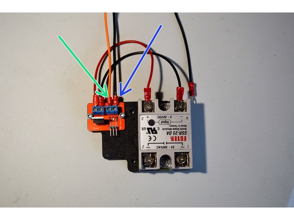
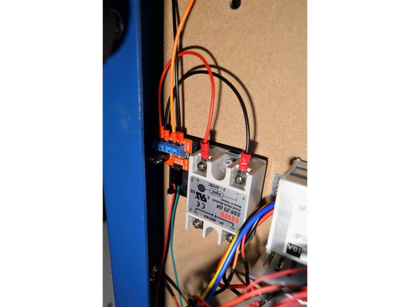
Insert the orange Toggle Switch Cable into the V_in terminal
-
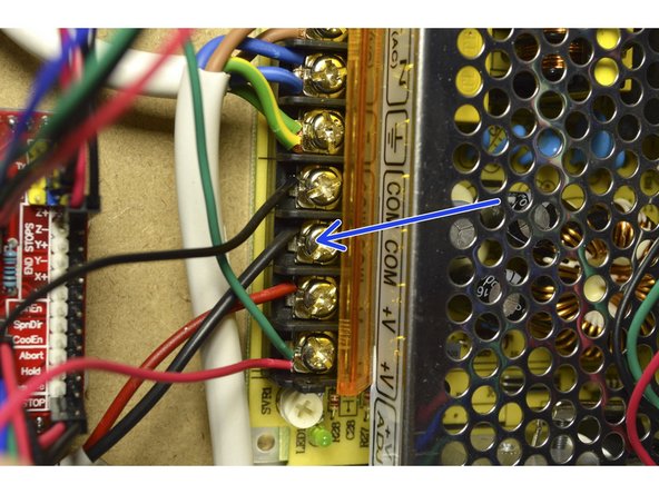
Insert the black Relay Power Ground Cable into the GND terminal on the mosfet and the other end on the 12V power supply
Hi where does the other end of the black relay power ground cable go?
Cobus Grobler - Resolved on Release Reply
Hi Cobus.
We have updated the instructions, thank you for letting us know. The black cable from the mosfet will go to the 12V ground on the power supply.
-
-
-
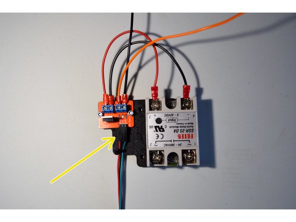
Connect the 3-pin connector of the Mosfet Signal Cable to the Mosfet board as shown
-
Make sure the green cable is on the right hand side and the red cable is on the left hand side
-
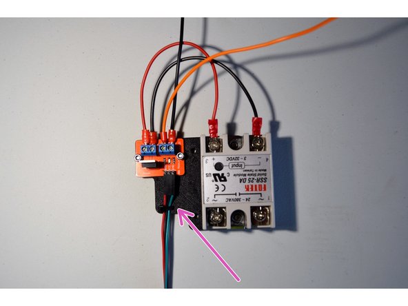
Cable tie the signal cable to the printed part through the holes provided
In spite of explanatory label, later mosfet switch cable with blue wire can be confusing as red and black wires are also transposed relative to picture. Suggest picture update.
Graham Bate - Resolved on Release Reply
-
-
-
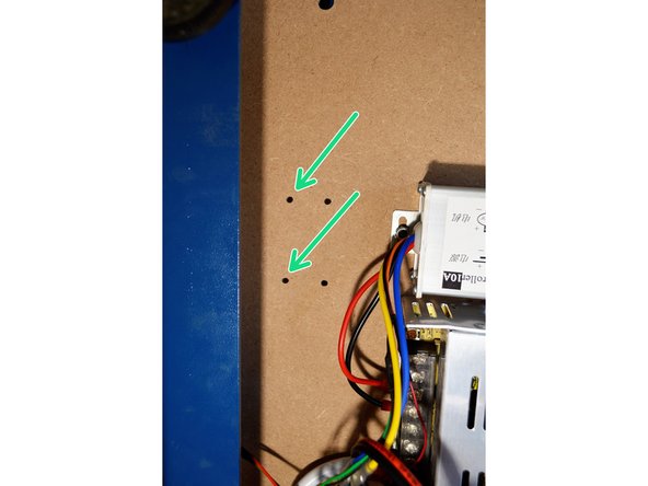
Use the 2 holes on the left hand side from the old relay to mount the new relay
-
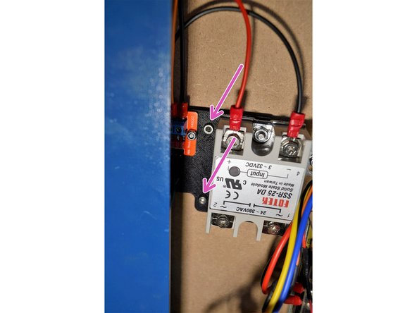
Mount the new relay with the 2 pcs M3x12 cap screws and M3 lock nuts as shown
My M3x12 Cap Screws are to short to mount the relay to the board. The M3 Cap Screws holding the Mosfet board are to long and in the way.
Nico Potgieter - Resolved on Release Reply
-
Cancel: I did not complete this guide.
5 other people completed this guide.


