
-
-
Laser Module 0.5W/2.5W or 5.5W
-
Taper laser mount
-
4 pcs M3x12 Cap Screws
-
Laser mounting bracket
-
1 pcs M4x12 Cap Screw
-
1 pcs M4 Lock Nut
-
Cable Holder
-
1 pcs M3x12 Cap Screw
-
-
-
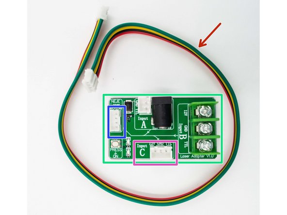
TTL, PWM, NEJE interface transfer board tester for laser module
-
Four pin laser line
-
The red cable is 12V, black cable is GND, the yellow cable is TTL and the green cable is Temperature
-
Input
-
Output
-
-
-
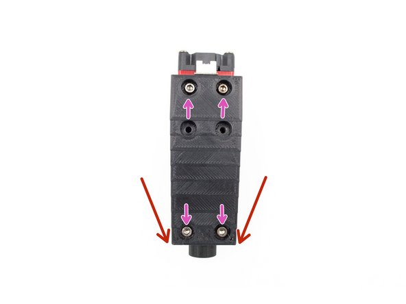
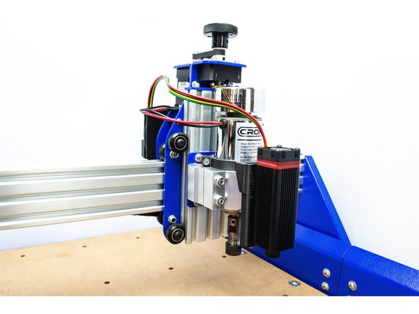
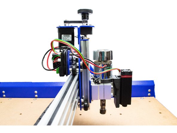
Mount the Taper laser mount to the laser with the taper towards the bottom as shown
-
Fix it with the four M3x12 cap screws
-
-
-
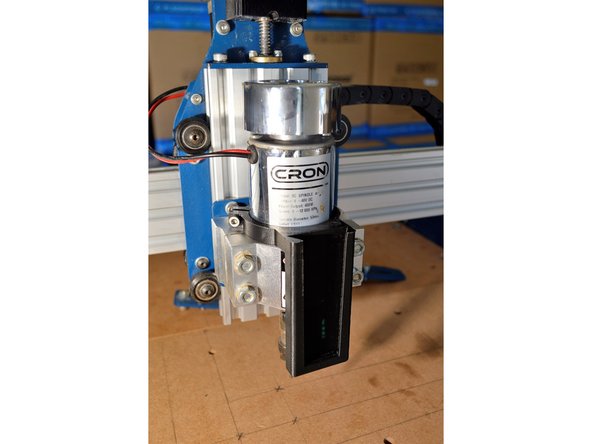
Mount the laser bracket to the spindle as shown
-
Make sure the bracket hooks onto the spindle bracket at the bottom
-
Clamp the bracket with the M4x12 cap screw and lock nut
-
-
-
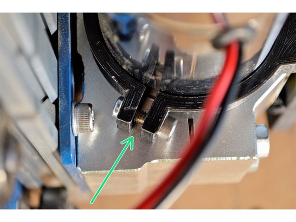
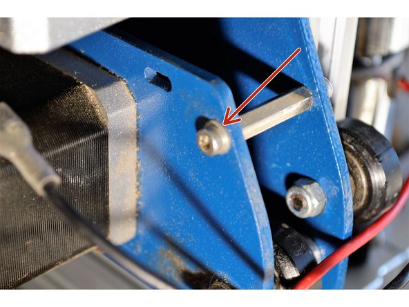
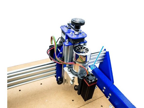
Remove the M3 screw and washer from the stand-off next to the X-motor
-
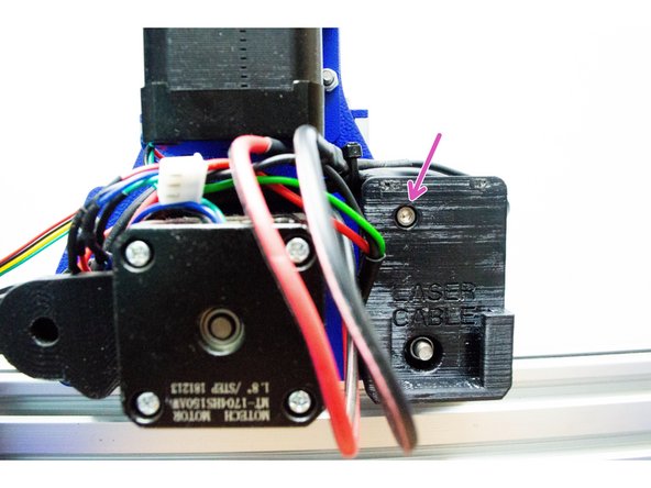
Mount the cable holder with the M3x12 cap screw as shown
-
The cable holder is used to secure the laser cable when the laser is removed from the machine
-
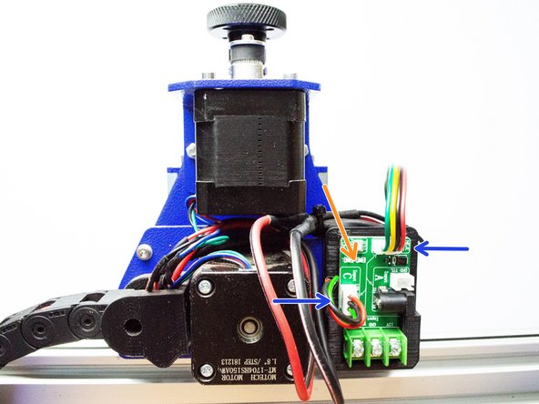
Slide the transfer board into the cable holder
-
Connect the tree point laser cable to the input and the four point cable to the output of the transfer board and make sure the cables are in the right order.
-
-
-
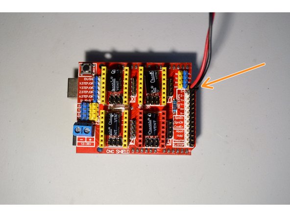
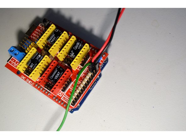
Connect the 2-pin connector from the mosfet board to the controller board as shown. It connects to the Z+ pins and the black cable connects to the black pin and the red cable to the white pin
-
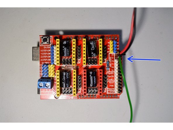
The green cable from the laser connector connects to the Z- pin. Please note it connects to the white pin as shown.
-
-
-
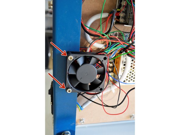
Mount the fan back onto the controller board with the original M4 screws and nuts
-
Now the wires can be neatend below the machine with the remaining cable ties. Please note that all the cables are designed for the large CNC machine, thus the small and medium machines will have extra long cables.
-


Cancel: I did not complete this guide.
4 other people completed this guide.
2 Comments
Impossible to slide the laser transfer board into the 3d printed holder without damaging the pcb. Now just dangling outside. Please revise this error.
Francois Maritz - Resolved on Release Reply