Difficulty
Easy
Steps
5
Time Required
00:05:00
- X-gantry assembly 5 steps

In Progress
This guide is currently being written. Reload periodically to see the latest changes.

Private
This guide will not appear in search results and can only be viewed by team members!
Quiz
0
-
-
Slide the aluminium profile onto the V-wheels of the spindle assembly with the logo on the profile in the same orientation as the spindle assembly.
-
-
-
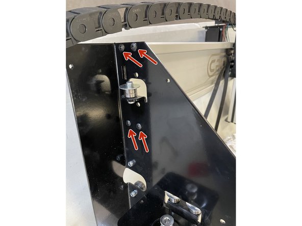
Remove the cover from the left gantry by unscrewing the 6 screws as shown in the pictures with the philips screw driver
-
-
-
Mount the left gantry to the left side of the aluminium profile with the 4 x M5x16 black button head cap screws.
-
Add a small drop of Pratley Pratlock to the screw thread before inserting the screws.
-
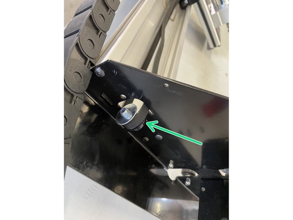
Hook the GT2 Timing belt over the idler pulley with the teeth of the belt to the inside.
-
-
-
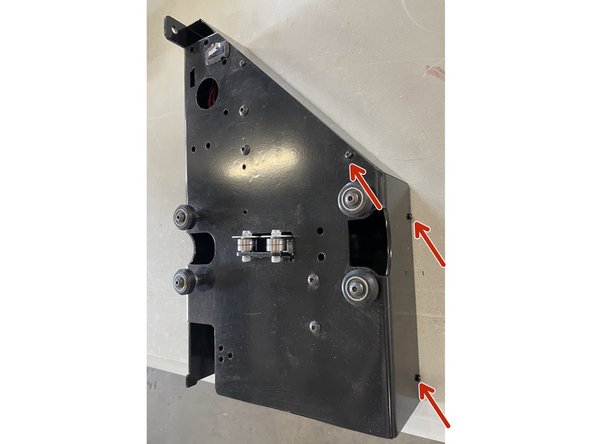
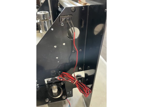
Remove the cover from the right gantry by unscrewing the 6 screws as shown in the pictures with the philips screw driver
-
-
-
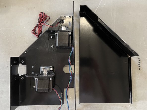
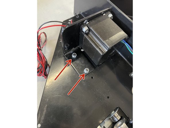
Remove the 2 screws holding the top motor inside the right gantry with the 3mm Allen Key and No 8 Spanner.
-
Mount the right gantry to the right side of the aluminium profile with 3 of the M5x16 black button head cap screws.
-
Add Pratley Pratlock to these screws.
-