Introduction
How to assemble the X-Gantry of the CRON Craft V2 CNC machine with 400W spindle and lead screw driven configuration.
Tools
-
-
Take the X-axis aluminium profile and the spindle assembly and check that the pre-load of the V-wheels are set correctly for this profile. Please refer to the video in Step 2 on how to set the preload of the V-Wheels.
-
Slide the aluminium profile onto the V-wheels of the spindle assembly with the logo on the profile in the same orientation as the spindle assembly.
-
You will see there is an extra cable in the drag chain, this is for the Laser Upgrade Kit. When you add the Laser Upgrade Kit later, you will use this cable.
-
-
-
In this video we discuss how to set the preload of the V-wheels. This need to be checked for each V-wheel assembly on the CNC machine.
-
-
-
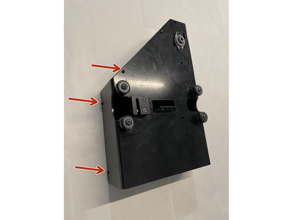
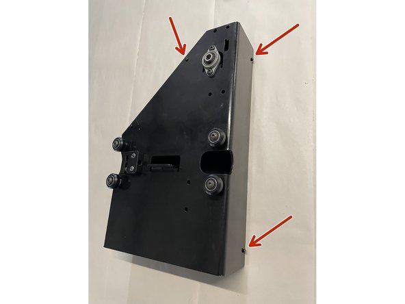
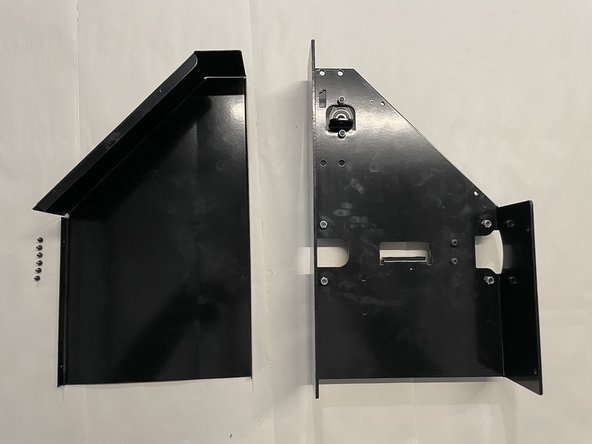
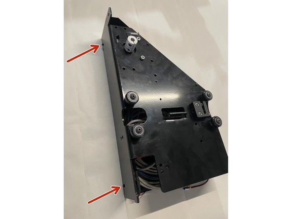
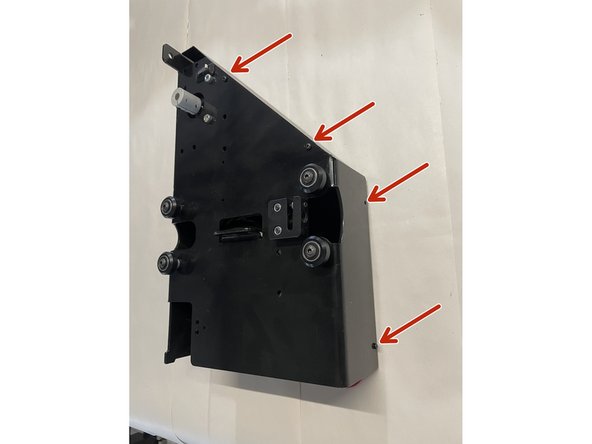
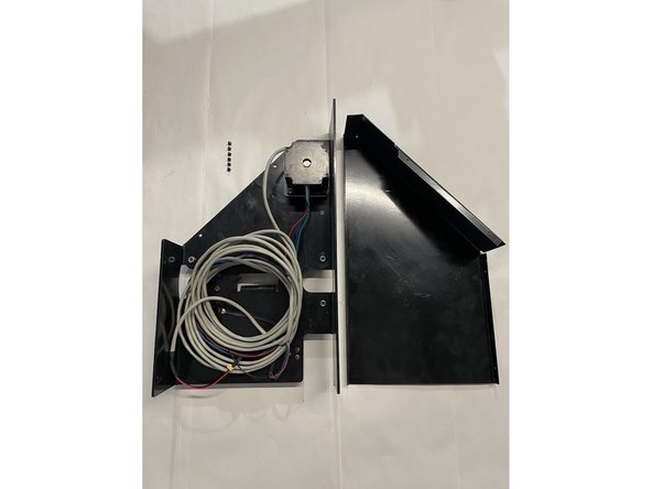
Remove the cover from the left gantry by unscrewing the 6 screws as shown in the pictures with the philips screw driver
-
-
-
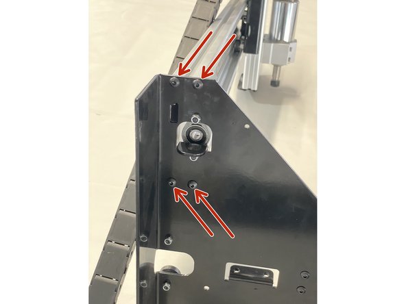
Mount the left gantry to the left side of the aluminium profile with the 4 x M5x16 black button head cap screws.
-
-
-
Remove the cover from the right gantry by unscrewing the 6 screws as shown in the pictures with the philips screw driver
-
-
-
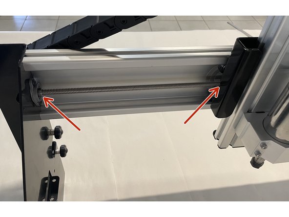
Turn the X-Axis Lead Screw into the Delrin Block on the back of the Spindle Assembly till you can push the lead screw through the pillow block bearing on the Left Gantry.
-
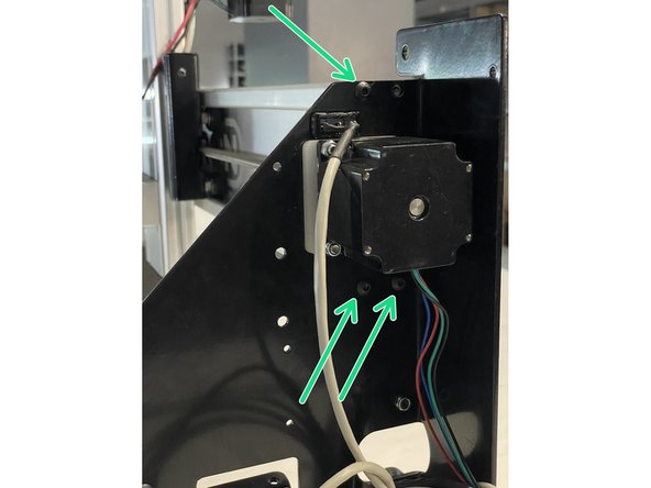
Mount the right gantry to the right side of the aluminium profile with 3 of the M5x16 black button head cap screws. (The 4th screw will be added later)
-
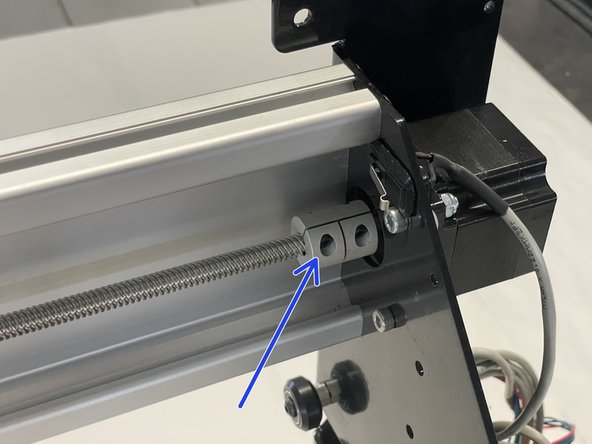
Slide the lead screw back into the rigid coupling mounted to the X-Motor and tighten the rigid coupling onto the lead screw with a 2.5mm Allen Key.
-
Tighten the two grub screws in the pillow block bearing on the left gantry holding the lead screw with a 1.5mm Allen Key.
-
-
-
Mount the M6x40 cap screw to the right gantry as shown in the picture with the M6 nut. For this you will need the 4mm Allen Key and the No 10 spanner.
-
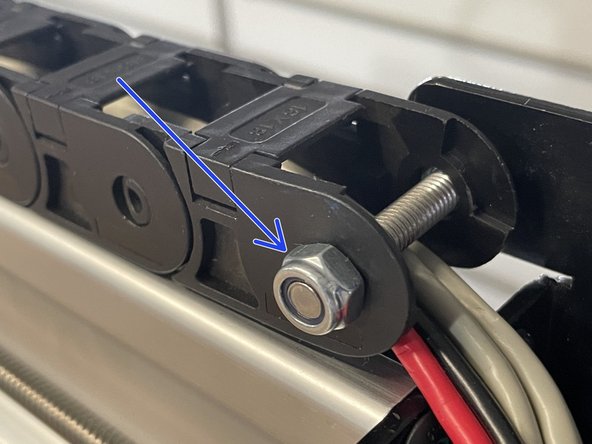
Slide the drag chain from the spindle assembly over the M6 screw with the cables below the screw.
-
Lock the drag chain in place with the M6 lock nut. Tighten the lock nut with the No 10 Spanner.
-
-
-
Fasten the green earth cable with a M5x16 black button head cap screw to the 4th hole into the aluminium profile.
-
-
-
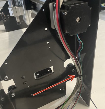
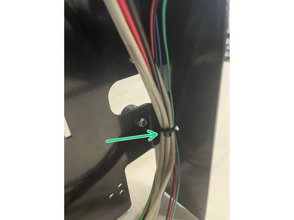
Route the cables through the right gantry as shown in the picture. Tighten them with a cable tie to the back of the right gantry.
-
Cut the tail of the cable tie off with a side cutter.
-


