
-
-
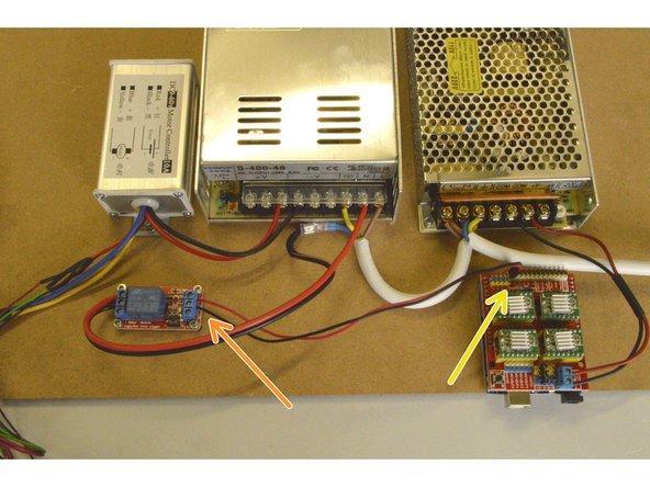
Spindle Speed Controller
-
Relay COM Cable
-
Relay 12V Cable
-
Relay Signal Cable (with 2 pin connector)
-
M4 Lock Nuts (2 Pcs)
-
M4x8 Cap Screw (2 Pcs)
-
-
-
3mm Allen Key
-
Small Phillips Screw Driver
-
Phillips Screw Driver
-
Sharp Nose Pliers
-
-
-
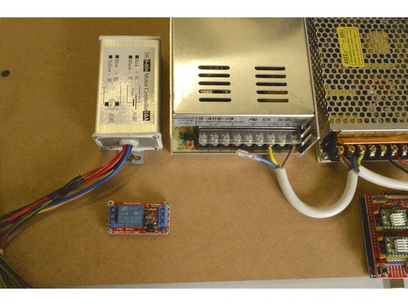
Mount the Spindle Speed Controller as shown with the M4x8 Cap Screws (2 Pcs) and the M4 Lock Nuts (2 Pcs)
-
Tighten the screws with the 3mm Allen Key and the Sharp nose pliers
-
-
-
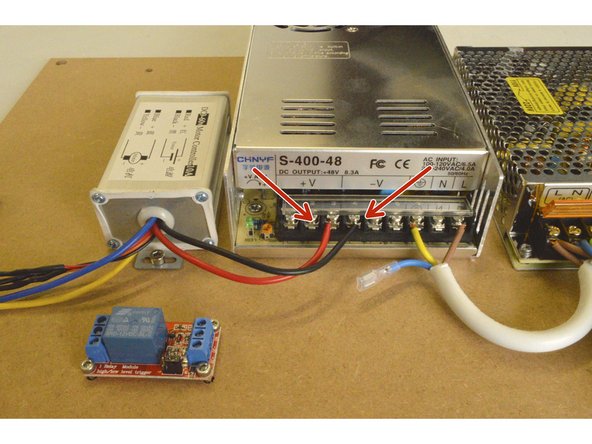
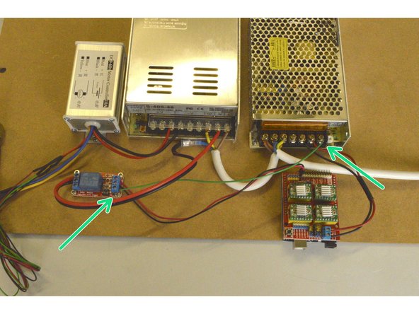
Connect the black and red cable of the Speed Controller to the V- and V+ port on the 400W power supply as shown
-
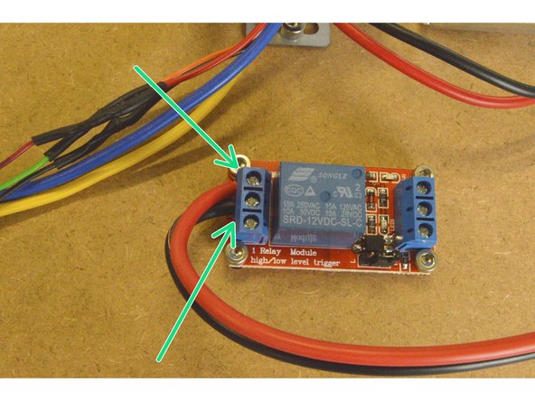
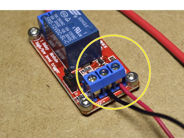
Take the Relay COM Cable and connect the end without the crimp terminal to the relay. The red cable needs to be connected to the NO port and the black cable to the COM port as shown.
-
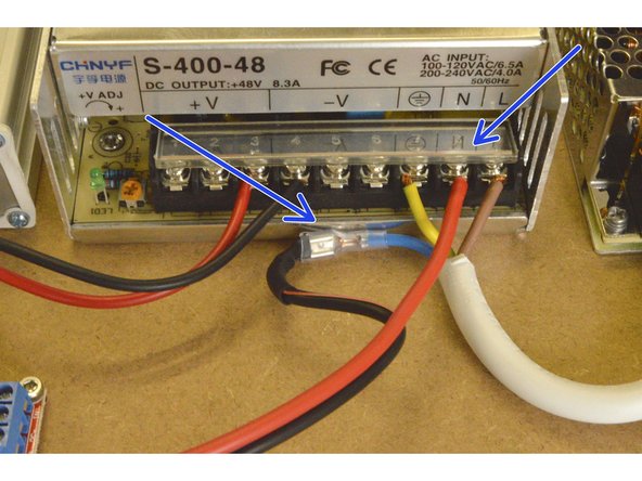
Connect the other end of the Relay COM cable to the 400W power supply by connecting the red cable to the N port and the black cable to the crimp terminal on the blue 220V cable as shown.
-
-
-
Connect the Relay Signal cable to the IN port on the relay (red cable) and to the DC- port on the relay (black cable)
-
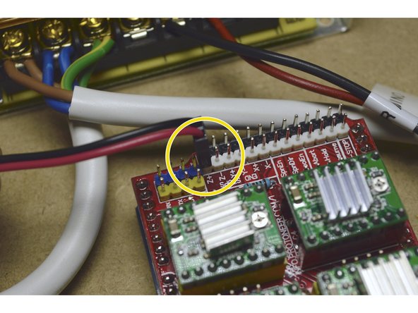
Plug the 2 pin connector to the Z+ pins on the CNC shield with the red cable closest to the stepper drivers as shown
-
-
-
Connect the Relay Power Cable to the DC+ port on the Relay and to the +V port on the 100W Power supply
-


Cancel: I did not complete this guide.
14 other people completed this guide.
One Comment
A bit vague this step when done in conjunction with the laser add on.
Francois Maritz - Resolved on Release Reply