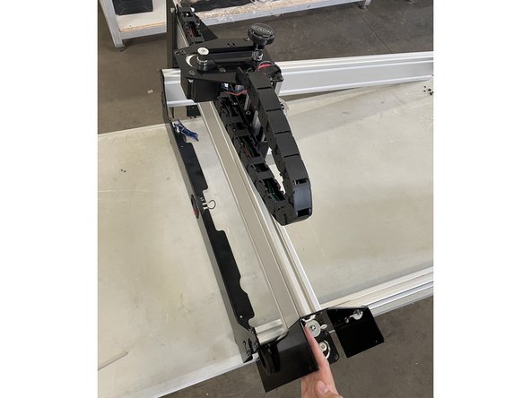
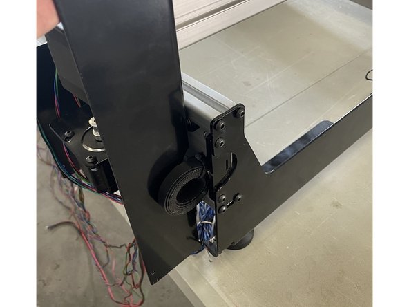
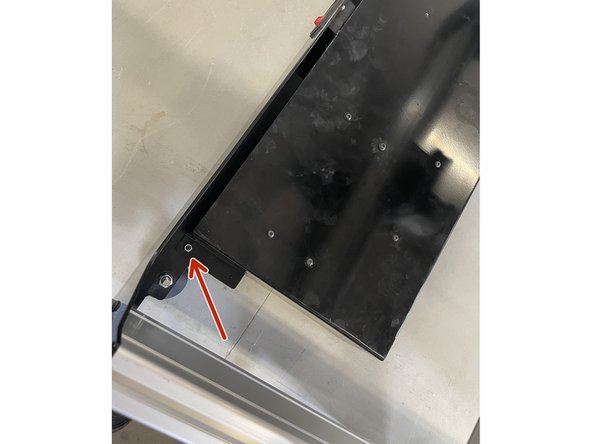
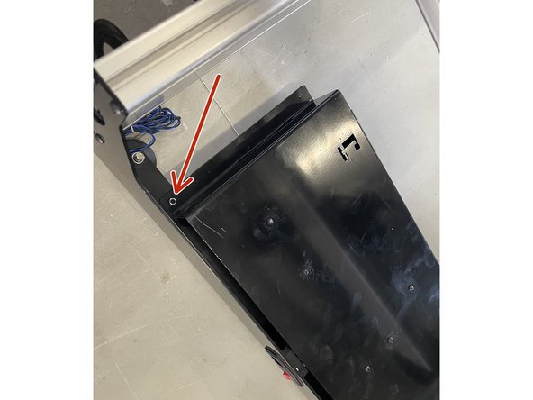
-
-
Take the Y-axis aluminium profiles and check the preload on the V-wheels for the Y-axis in the exact same way as we did for the X-axis.
-
Use the one profile for the left gantry and the other one for the right gantry.
-
Leave the aluminium profiles on the V-wheels after you checked the preload.
-
-
-
Mount the 2 long aluminium profiles to the back plate with 8 x M5x16 black button head cap screws as shown in the pictures.
-
Do not fully tighten these screws at this stage.
-
-
-
Slide the X-Gantry assembly onto the aluminium profiles and slide it all the way to the Back Plate.
-
While the X-Gantry is against the back plate, tighten the 8 x M5x16 black button head cap screws.
-
-
-
Mount the Electronics Assembly to the back plate with 2 x M5x12 Button head cap screws and 2 x M5 lock nuts as shown in the pictures.
-
-
-
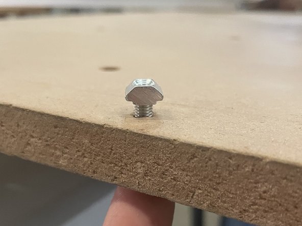
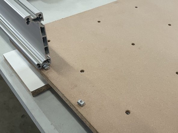
Add 10 x M5x20 cap screws and 10 x M5 T-Nuts to each waste board as shown in the pictures.
-
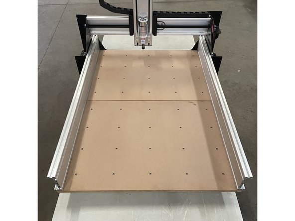
If you have the medium machine you will have 1 waste board. If you have the large machine you will have 2 waste boards.
-
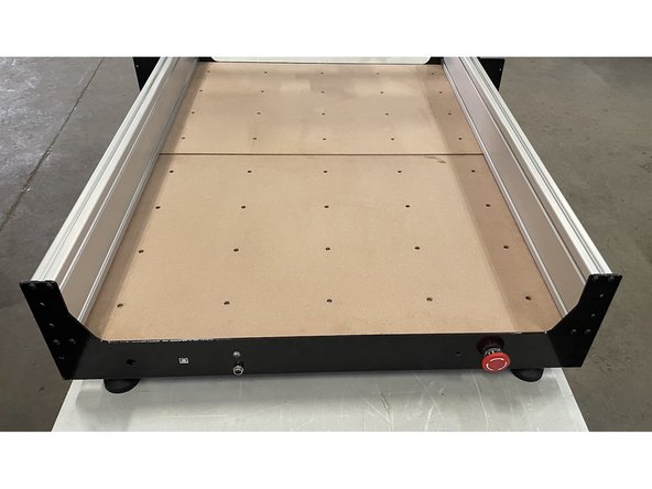
Slide the waste board(s) onto the aluminium profiles as shown in the pictures. Do not tighten these screws at this stage.
-
-
-
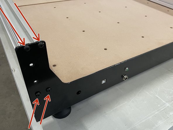
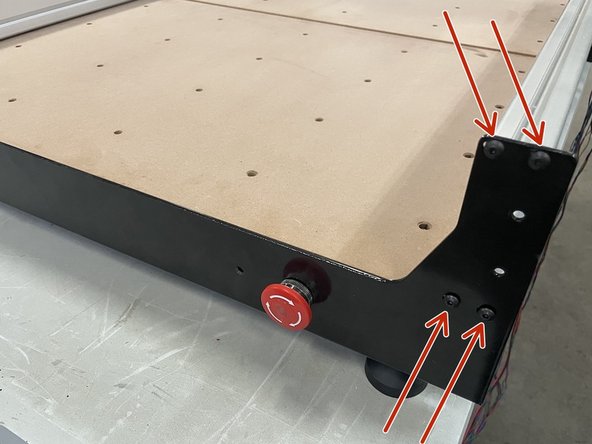
Mount the front plate to the aluminium profiles with 8 x M5x16 black button head cap screws as shown in the pictures.
-
Do not tighten these screws at this stage.
-
-
-
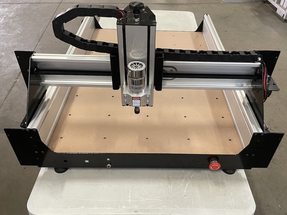
Slide the X-Gantry to the front against the front plate and tighten the 8 x M5x16 button head cap screws holding the front plate.
-
Now, fully tighten all the M5x20 cap screws holding the waste board(s).
-
-
-
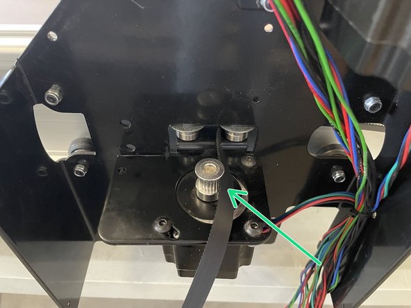
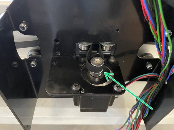
Take the 10mm GT2 belt mounted to the back plate and route it around the bearings and pulley in the left and right gantries and to the front plate.
-
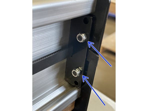
Take the end of the belt and feed it through the slot in the Belt Clamping Plate. Fasten the belt to the front plate by clamping the belt between the Belt Clamping Plate and the Front Plate with 2 x M5x12 black button head cap screws and 2 x M5 lock nuts.
-
Pull the end of the belt with sharp nose pliers to tension the belt while you tighten the screws so that you tension the belt.
-
Repeat for the other side with another Belt Clamping Plate, 2 x M5x12 black button head cap screws and 2 x M5 lock nuts.
-
Cut the pieces of belt sticking out off on the edge of the frame.
-
Almost done!
Finish Line


