
-
-
CNC Frame
-
Electronics Assembly
-
Waste Board: Small (1 Pcs), Medium (2 Pcs), Large (3 Pcs)
-
M6x16 Cap Screw: Small (6 Pcs), Medium (12 Pcs), Large (18 Pcs)
-
M6 Washer: Small (6 Pcs), Medium (12 Pcs), Large (18 Pcs)
-
-
-
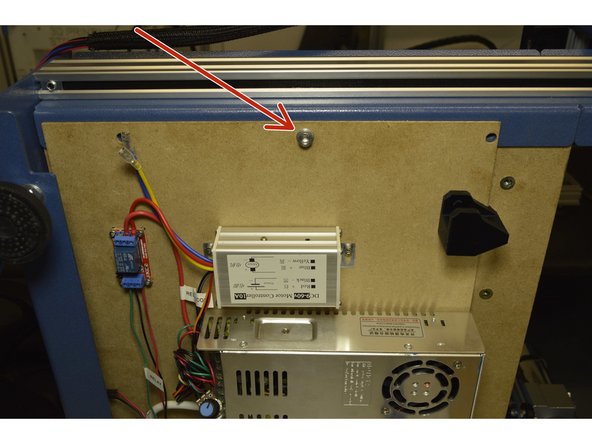
Mount the Electronics assembly from the bottom and the waste board from the top with one M6x16 Cap Screw, M6 Washer and Pratley Pratlock
-
Only hand tighten the screw at this stage.
-
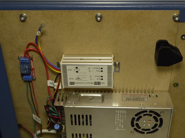
Insert the other 5 pcs M6x16 Cap Screws and M6 Washers with Pratley Pratlock. Only hand tighten these screws.
-
-
-
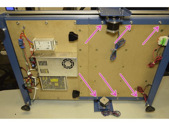
This step is not required for the Small CNC machine
-
Mount the other waste board(s) with the remaining M6x16 Cap Screws, M6 Washers and Pratley Pratlock
-
First only hand tighten the screws. After all the screws has been inserted, only then tighten all the M6x16 screws with the 5mm Allen Key.
-
If the allighment is out by so much that the M6x16 screws do not line up, check the alignment of the frame. It might mean that you need to loosen the screws holding the frame to change the alignment.
-
-
-
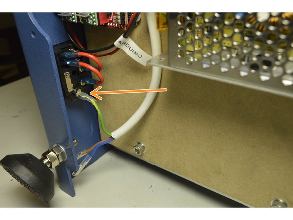
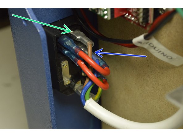
Connect the Green and Yellow cable of the 220V Power Cable to the bottom port on the kettle plug as shown
-
Connect the blue cable to the port second from the top on the kettle port
-
Connect the Brown cable to the top port on the kettle plug
-
-
-
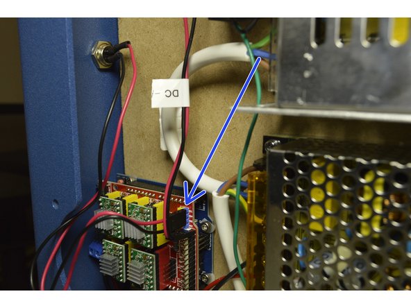
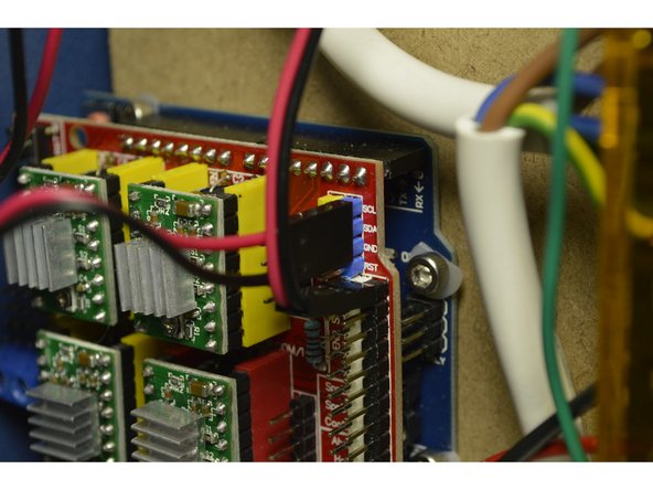
Connect the cable from the GX12 connector on the back panel to the Electronics module
-
The red cable goes on the SCL pin and the black cable goes on the GND pin
-
The middle pin will not be connected to anything
-
-
-
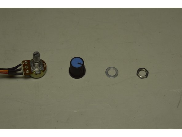
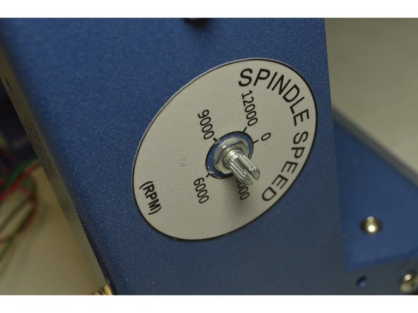
Disassemble the knob from the spindle speed controller
-
Mount the adjustment knob through the hole in the from pannel and fix it with the washer and nut provided while adding Pratley Pratlock
-
Tighten the nut with the sharp nose pliers to make sure the adjustment knob is fixed to the frame
-
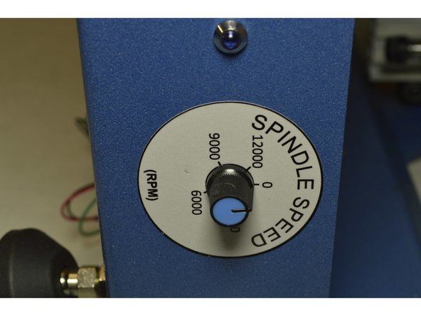
Turn the knob anti-clockwise as far as it can
-
Push the knob back onto the adjustment knob so that the line aligns with the zero on the spindle speed sticker
-


Cancel: I did not complete this guide.
13 other people completed this guide.
2 Comments
My 100W 12V power supply only has 5 ports. Where does the black E Stop cable go? I cannot get hold of anybody. johanbkopanokwik@gmail.com. can you advise who or where to ask?
Johan -