-
-
Move the X-gantry to the middle of the machine and the spindle to the left of the machine and turn the machine on its side.
-
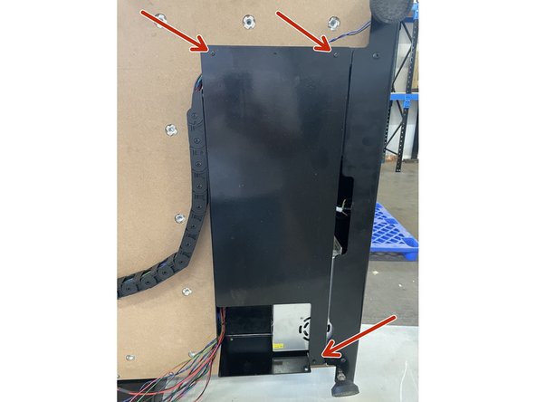
Use a 2mm Allen Key and remove the 3 screws holding the Electronics Assembly Cover.
-
-
-
Use a Flat Screw Driver and open all the links of the Y-Drag Chain if not done so already.
-
There is a small screw driver sign on the drag chain, this is where you need to open the links.
-
This can be done by pressing the screw driver into the slot and turning the screw driver.
-
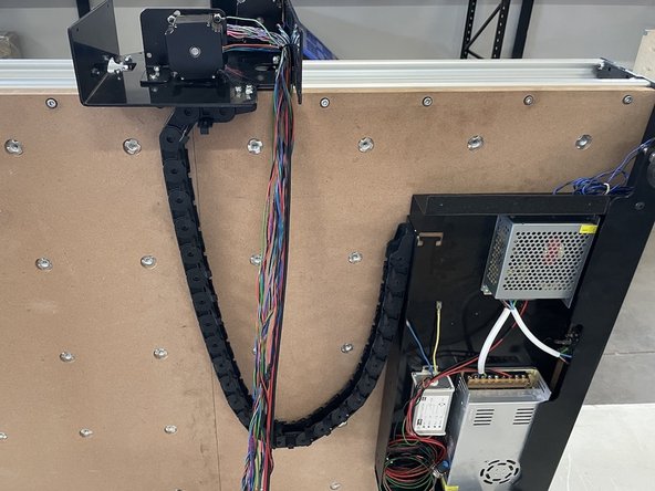
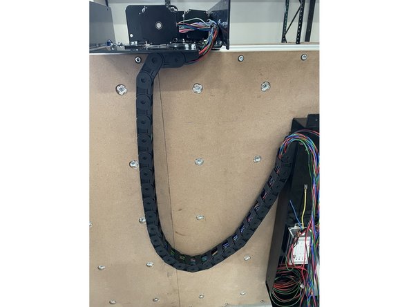
If you are building the Medium size CNC machine: Remove 4 of the linkages in the middle of the drag chain to make the drag chain slightly shorter.
-
If you are building the Large size CNC machine: Use the drag chain as is.
-
-
-
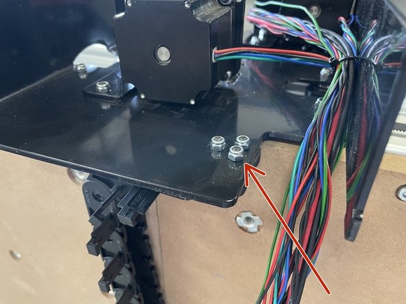
Mount the drag chain to the Right Gantry with 3 x M4x12 Counter Sunk Screws and 3 x M4 Lock Nuts. Use the 2.5mm Allen Key and No.7 Spanner to do this.
-
The drag chain can only be fastened in one orientation due to the spacing of the holes. So if the 3 holes in the drag chain does not line up with the holes in the steel plate, flip the drag chain around.
-
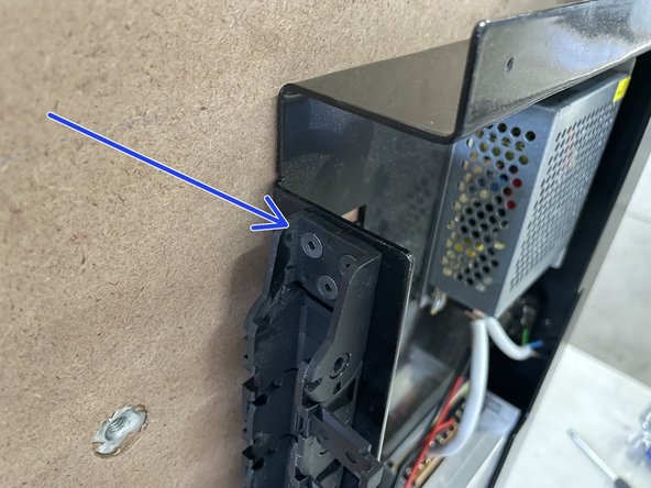
Mount the other side of the drag chain to the Electronics Assembly with 3 x M4x12 Counter Sunk Screws and 3 x M4 Lock Nuts.
-
-
-
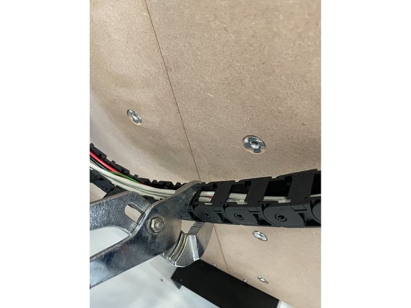
Close the links of the drag chain by pressing them closed one by one. Make sure all the wires from the Right Gantry runs inside the drag chain.
-
Groove Joint Pliers works well to close the drag chain.
-
-
-
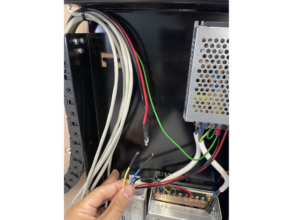
Route the Y-End stop cable through the same gap in the Electronics Assembly as the wires from the drag chain.
-
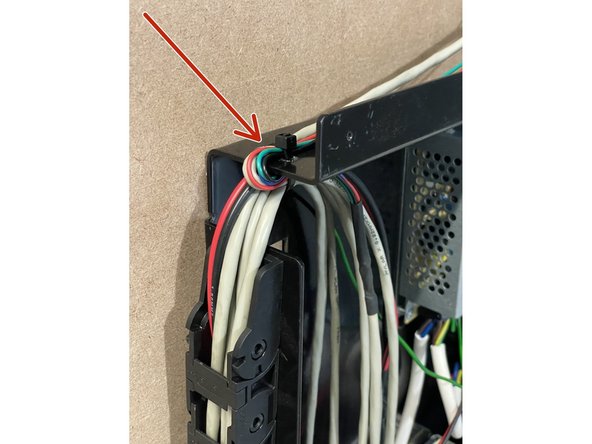
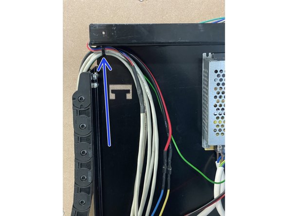
Use a 2.5mm cable tie to tie the cables to the Electronics Assembly Base Plate through the holes provided.
-
Make sure the Y-End stop cable is tied down on the outside of the base plate and then joins the cables from the drag chain.
-
All the wires are tied down on the inside of the base plate with the same cable tie as shown in the pictures.
-
-
-
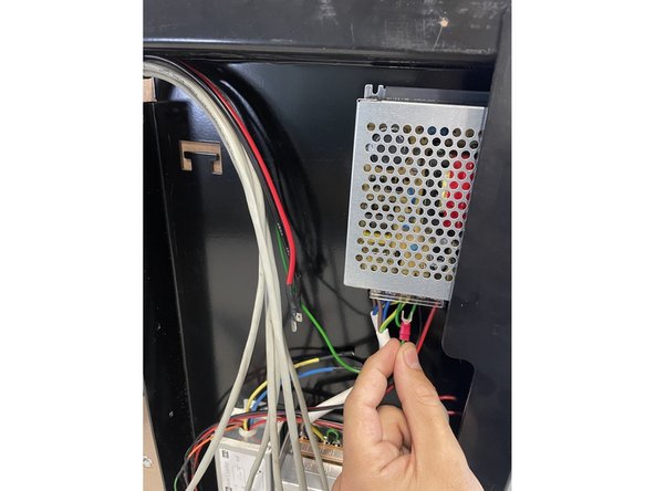
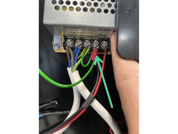
Connect the green ground cable to the earth connection of the 24V power supply.
-
This can be done by loosening the screw of the earth connection with a Phillips Screw Driver. Then sliding the fork terminal in below the plate in the connection and tightening the screw again.
-
Make sure the green and yellow cables in that connection stay in place when you do this.
-
-
-
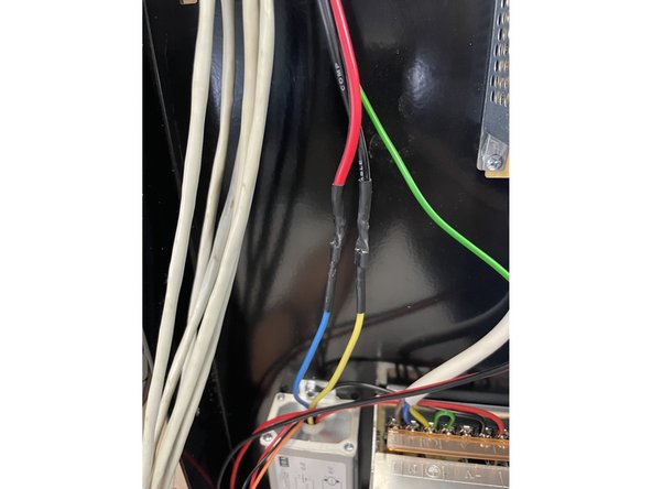
Connect the spindle cable (red and black cables) to the blue and yellow cables from the speed controller as shown in the picture.
-
The red wire connects to the blue wire and the black wire connects to the yellow wire.
-
-
-
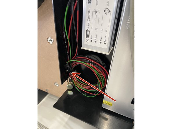
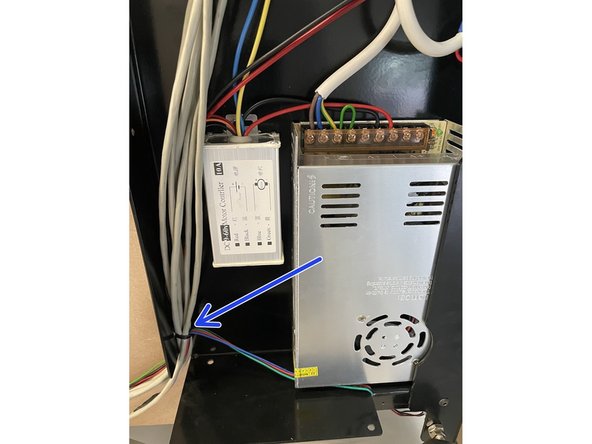
There is a spool of wires tied to the bottom of the Electronics Assembly. Cut the cable tie off with a side cutter and add these wires to the wires coming from the drag chain.
-
Tie the wiring inside the Electronics Assembly down to the base plate with a 2.5mm cable tie as shown in the pictures.
-
-
-
Connect the white 3-core cable to the kettle plug as shown in the picture.
-
-
-
Mount the cover of the Electronics Assembly back in place with the 3 M3x6mm Button Head Screws that was removed previously.
-
-
-
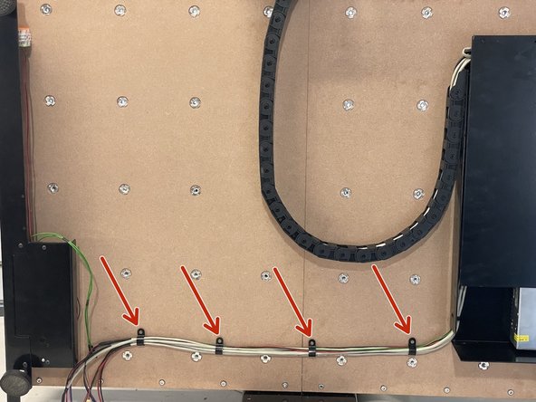
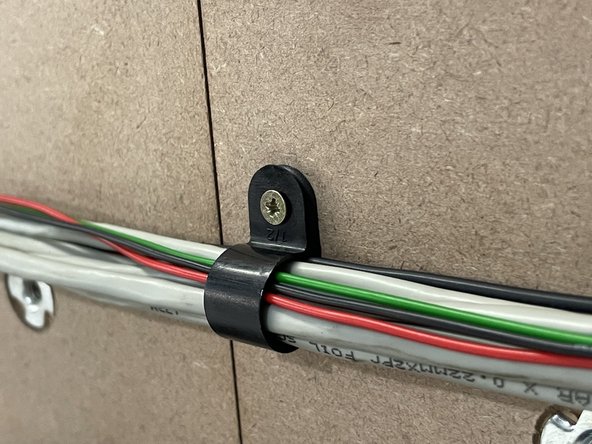
Tie the wiring down to the waste board(s) with the 4 x P-Clamps and 4 x 3x13mm Chipboard screws by screwing the chipboard screws into the waste board(s) with a phillips screw driver. The wiring should run in a straight line from the Electronics Assembly to the Front Plate.
-
The wiring for the Medium machines will be longer than needed and you will only need 2 x P-Clamps. So the other 2 x P-Clamps can be used to make a circle with the wiring and fasten it to the waste board.
-
-
-
Remove the Arduino Assembly Cover on the Front Plate by removing the two M4x8 screws holding the plate. You will need a 2.5mm Allen Key and a No. 7 spanner for this.
-
-
-
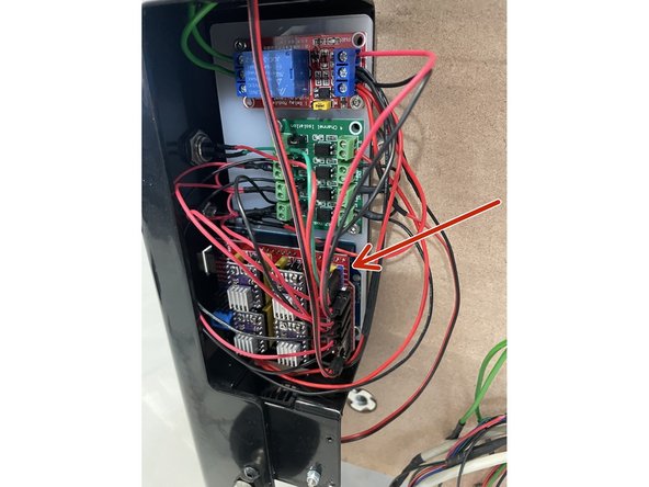
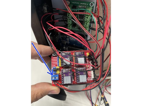
Remove the CNC shield from the Arduino board. The CNC Shield is the red board in the bottom of the picture with a lot of wires connected to it. It can be removed by carefully pulling it towards you.
-
On the bottom left corner of the board is the power connector. Connect the open ended red & black power cable coming from the 100W power supply to the red & black port respectively. There are already other wires in that connector, so make sure those wires stay in that connector.
-
When you are done, put the CNC shield board back in place on top of the Arduino board. Make sure all the pins slide into the Arduino headers when you do that.
-
-
-
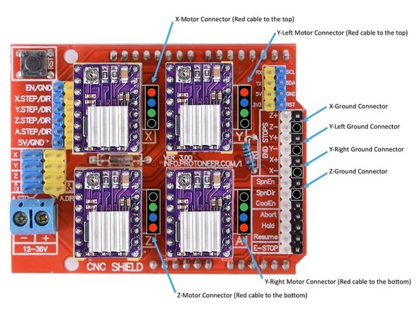
Connect the X-Motor connector to the X-Motor pins on the Arduino with the red wire to the top. Connect the X-Ground connector to the ground pin as shown in the picture.
-
Connect the YL-Motor connector to the Y-Motor pins on the Arduino with the red wire to the top. Connect the YL-Ground connector to the ground pin as shown in the picture.
-
Connect the YR-Motor connector to the A-Motor pins on the Arduino with the red wire to the bottom. Connect the YR-Ground connector to the ground pin as shown in the picture.
-
Connect the Z-Motor connector to the Z-Motor pins on the Arduino with the red wire to the bottom. Connect the Z-Ground connector to the ground pin as shown in the picture.
-
Leave all the other connectors in place as it was.
-
-
-
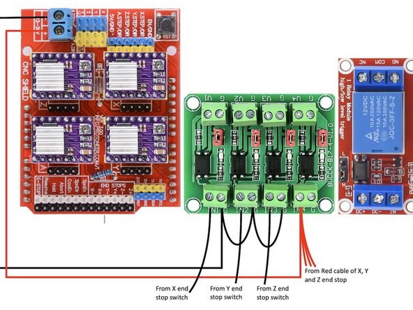
Connect the X, Y and Z end stop switch cables coming from the end stop switches to the green opto-isolator board as shown in the picture. Each cable consist of a black and a red wire.
-
Keep the already connected wires as is.
-
-
-
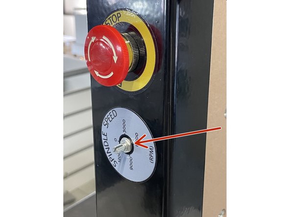
Remove the knob, nut and washer from the potentiometer connected to the speed control and mount it in the front panel next to the E-Stop button. Turn the potentiometer anti-clockwise till it stops and put the knob back with the line on zero.
-
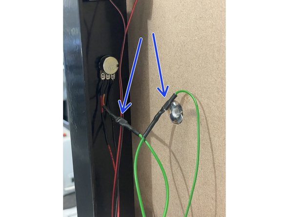
Connect the orange and green cables with the spade connector to the green cables coming from the relay. The male and female connectors will show you which one is connected to which.
-
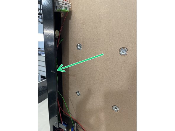
Tie the cables going to the potentiometer and E-Stop to the Front plate with a 2.5mm cable tie in the holes provided as shown in the picture.
-
-
-
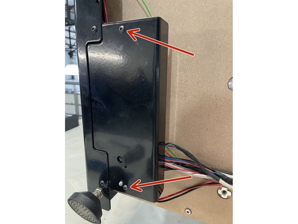
Mount the Arduino Cover Plate back over the Arduino assembly with the M4 screws you removed when you took it off.
-
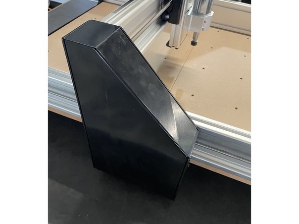
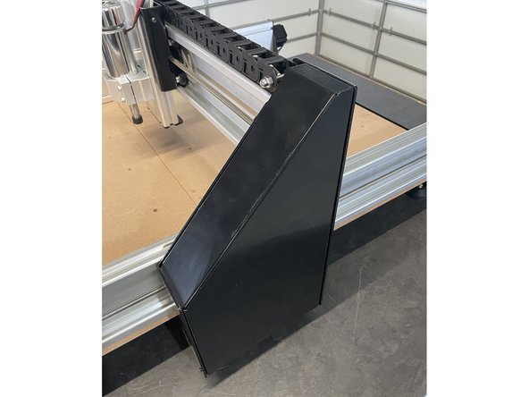
Turn the machine back on its feet and mount the left and the right Gantry Cover Plates back to the left and the right gantries with the screws they were fastened with. Each cover plate is fastened with 6 x black self tapping screws.
-
Now you can follow the Software Setup Guide in the User Manual to install the required software.
-
Almost done!
Finish Line


